Download as a PDF »
The electronics industry is continually shifting. Device density and technology is more complex. Electronics manufacturing is more heavily reliant on out-sourcing. The ESD industry seems to have jumped into this swirling eddy headfirst. ESD control programs have mushroomed. Black has been replaced by green, blue and gold. Shielding bags dominate the warehouse. Ionizers exist along side wrist straps and ground cords. An early history of “smoke and mirrors,” magic and lofty claims of performance is rapidly and safely being relegated to the past.
Today, more than ever, meeting the complex challenge of reducing ESD losses requires more than reliance on faith alone. Users require a way to legitimately evaluate and compare competing brands and types of products. They need objective confirmation that their ESD control program provides effective solutions to their unique ESD problems. Contract manufacturers and OEM’s require mutually agreed-upon ESD control programs that reduce duplication of process controls.
That’s where standards come into play. They provide guidance in developing programs that effectively address ESD process control. They help define the sensitivity of the products manufactured and used. They help define the performance requirements for various ESD control materials, instruments, and tools. Standards are playing an ever-increasing role in reducing marketplace confusion in the manufacture, evaluation, and selection of ESD control products and programs.
The Who and Why of Standards
Who uses ESD standards? Manufacturers and users of ESD sensitive devices and products, manufacturers and distributors of ESD control products, certification registrars, and third party testers of ESD control products.
Why use ESD standards? They help assure consistency of ESD sensitive products and consistency of ESD control products and services. They provide a means of objective evaluation and comparison among competitive ESD control products. They help reduce conflicts between users and suppliers of ESD control products. They help in developing, implementing, auditing, and certifying ESD control programs. And, they help reduce confusion in the marketplace.
In the United States, the use of standards is voluntary, although their use can be written into contracts or purchasing agreements between buyer and seller. In most of the rest of the world, the use of standards, where they exist, is compulsory.
Key Standards and Organizations
Just 20 years ago, there were relatively few reliable ESD standards and few ESD standards development organizations. Today’s ESD standards landscape is not only witnessing an increase in the number of standards, but also increasing cooperation among the organizations that develop them.
Today’s standards fall into three main groups. First, there are those that provide ESD program guidance or requirements. These include documents such as ANSI ESD S20.20-2007–Standard for the Development of an ESD Control Program, ANSI/ESD S8.1-Symbols-ESD Awareness , or ESD TR20.20-ESD Handbook.
A second group covers requirements for specific products or procedures such as packaging requirements and grounding. Typical standards in this group are ANSI/ESD S6.1-Grounding and ANSI/ESD S541 –Packaging Materials for ESD Sensitive Items.
A third group of documents covers the standardized test methods used to evaluate products and materials. Historically, the electronics industry relied heavily on test methods established for other industries or even for other materials (e. g., ASTM-257-DC Resistance or Conductance of Insulating Materials). Today, however, specific test method standards focus on ESD in the electronics environment, largely as a result of the ESD Association’s activity. These include standards such as ANSI/ESDA-JEDEC JS-001-2010-Device Testing, Human Body Model and ANSI/ESD STM7.1: Floor Materials — Resistive Characterization of Materials to cite just a few.
Who Develops Standards?
Standards development and usage is a cooperative effort among all organizations and individuals affected by standards. There are several key ESD standards development organizations.
Military Standards
Traditionally, the U.S. military spearheaded the development of specific standards and specifications with regard to ESD control in the U.S. Today, however, U.S. military agencies are taking a less proactive approach, relying on commercially developed standards rather than developing standards themselves. For example, the ESD Association completed the assignment from the Department of Defense to convert MIL-STD-1686 into a commercial standard called ANSI/ESD S20.20.
ESD Association
The ESD Association has been a focal point for the development of ESD standards in recent years. An ANSI-accredited standards development organization, the Association is charged with the development of ESD standards and test methods. The Association also represents the US on the International Electrotechnical Commission (IEC) Technical Committee 101-Electrostatics.
The ESD Association has published 36 standards documents and 23 Technical Reports. These voluntary standards cover the areas of material requirements, electrostatic sensitivity, and test methodology for evaluating ESD control materials and products. In addition to standards documents, the Association also has published a number of informational advisories. Advisory documents may be changed to other document types in the future.
ESD Association Standards Classifications and Definitions
There are four types of ESD Association standards documents with specific clarity of definition. The four document categories are consistent with other standards development organizations. These four categories are defined below.
- Standard: A precise statement of a set of requirements to be satisfied by a material, product, system or process that also specifies the procedures for determining whether each of the requirements is satisfied.
- Standard Test Method: A definitive procedure for the identification, measurement and evaluation of one or more qualities, characteristics or properties of a material, product, system or process that yields a reproducible test result.
- Standard Practice: A procedure for performing one or more operations or functions that may or may not yield a test result. Note: If a test result is obtained, it may not be reproducible between labs.
- Technical Report: A collection of technical data or test results published as an informational reference on a specific material, product, system, or process.
As new documents are approved and issued, they will be designated into one of these four new categories. Existing documents have been reviewed and have been reclassified as appropriate. Several Advisory Documents still exist and may be migrated to either Technical Reports or Standard Practices in the future.
International Standards
The international community, led by the European-based International Electrotechnical Commission (IEC), has also climbed on board the standards express. IEC Technical Committee 101 has released a series of documents under the heading IEC 61340. The documents contain general information regarding electrostatics, standard test methods, general practices and an ESD Control Program Development Standard that is technically equivalent to ANSI/ESD S20.20. A Facility Certification Program is also available. Global companies can seek to become certified to both ANSI/ESD S20.20 and to IEC61340-5-1 if they so choose. Japan also has released its proposed version of a national electrostatic Standard, which also shares many aspects of the European and U.S. documents.
Organizational Cooperation
Perhaps one of the more intriguing changes in ESD standards has been the organizational cooperation developing between various groups. One cooperative effort was between the ESD Association and the U.S. Department of Defense, which resulted in the Association preparing ANSI/ESD S20.20 as a successor to MIL-STD-1686. A second cooperative effort occurred between the ESD Association and JEDEC, which started with an MOU and resulted in the development of 2 documents: a joint HBM document was published in 2010; a joint CDM document will be published in 2011.
Internationally, European standards development organizations and the ESD Association have developed working relationships that result in an expanded review of proposed documents, greater input, and closer harmonization of standards that impact the international electronics community.
For users of ESD standards, this increased cooperation will have a significant impact. First, we should see standards that are technically improved due to broader input. Second, we should see fewer conflicts between different standards. Finally, we should see less duplication of effort.
Summary
For the electronics community, the rapid propagation of ESD standards and continuing change in the standards environment mean greater availability of the technical references that will help improve ESD control programs. There will be recommendations to help set up effective programs. There will be test methods and specifications to help users of ESD control materials evaluate and select products that are applicable to their specific needs. And there will be guidelines for vendors of ESD products and materials to help them develop products that meet the real needs of their customers.
Standards will continue to fuel change in the international ESD community.
Sources of Standards
ESD Association, 7900 Turin Road, Building 3, Rome, NY 13440. Phone: 315-339-6937. Fax: 315-339-6793. Web Site: http://www.esda.org
IHS Global Engineering Documents, 15 Inverness Way East, Englewood, CO 80112. Phone: 800-854-7179. Fax: 303-397-2740. Web Site: http://global.ihs.com
International Electrotechnical Commission, 3, rue de Varembe, Case postale 131, 1211 Geneva 20, Switzerland. Fax: 41-22-919-0300. Web Site: http://www.iec.ch/
Military Standards, Naval Publications and Forms Center, 5801 Tabor Avenue, Philadelphia, PA 19120
JEDEC Solid State Technology Association, 3103 North 10th Street, Suite 240-S
Arlington, VA 22201-2107, http://www.jedec.org
Principle ESD Standards
U.S. Military/Department of Defense
MIL-STD-1686C: Electrostatic Discharge Control Program for Protection of Electrical and Electronic Parts, Assemblies and Equipment (Excluding Electrically Initiated Explosive Devices) This military standard establishes requirements for ESD Control Programs. It applies to U.S. military agencies, contractors, subcontractors, suppliers and vendors. It requires the establishment, implementation and documentation of ESD control programs for static sensitive devices, but does NOT mandate or preclude the use of any specific ESD control materials, products, or procedures. It is being updated and converted to a commercial standard by the ESD Association. Although DOD has accepted the new ANSI/ESD S20.20 document as a successor, it has not yet taken action to cancel STD-1686
MIL-HBDK-263B: Electrostatic Discharge Control Handbook for Protection of Electrical and Electronic Parts, Assemblies and Equipment (Excluding Electrically Initiated Explosive Devices)
This document provides guidance, but NOT mandatory requirements, for the establishment and implementation of an electrostatic discharge control program in accordance with the requirements of MIL-STD-1686.
MIL-PRF 87893—Workstation, Electrostatic Discharge (ESD) Control
This document defines the requirements for ESD protective workstations.
MIL-PRF-81705—Barrier Materials, Flexible, Electrostatic Protective, Heat Sealable
This documents defines requirements for ESD protective flexible packaging materials.
MIL-STD-129—Marking for Shipment and Storage
Covers procedures for marketing and labeling ESD sensitive items.
ESD Association
Standards Documents
ANSI/ESD S1.1: Evaluation, Acceptance, and Functional Testing of Wrist Straps
A successor to EOS/ESD S1.0, this document establishes test methods for evaluating the electrical and mechanical characteristics of wrist straps. It includes improved test methods and performance limits for evaluation, acceptance, and functional testing of wrist straps.
ANSI/ESD STM2.1: Resistance Test Method for Electrostatic Discharge Protective Garments
This Standard Test Method provides test methods for measuring the electrical resistance of garments used to control electrostatic discharge. It covers procedures for measuring sleeve-to-sleeve and point-to-point resistance.
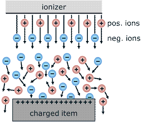
ANSI/ESD STM3.1-: Ionization
Test methods and procedures for evaluating and selecting air ionization equipment and systems are covered in this standard. The document establishes measurement techniques to determine ion balance and charge neutralization time for ionizers.
ANSI/ESD SP3.3: Periodic Verification of Air Ionizers.
This Standard Practice provides test methods and procedures for periodic verification of the performance of air ionization equipment and systems (ionizers).
ANSI/ESD S4.1: Worksurfaces – Resistance Measurements
This Standard establishes test methods for measuring the electrical resistance of worksurface materials used at workstations for protection of ESD susceptible items. It includes methods for evaluating and selecting materials, and testing new worksurface installations and previously installed worksurfaces.
ANSI/ESD STM4.2: Worksurfaces – Charge Dissipation Characteristics
This Standard Test Method provides a test method to measure the electrostatic charge dissipation characteristics of worksurfaces used for ESD control. The procedure is designed for use in a laboratory environment for qualification, evaluation or acceptance of worksurfaces.
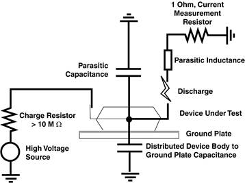
ESDA-JEDEC JS-001: Electrostatic Discharge Sensitivity Testing — Human Body Model
This Standard Test Method updates and revises an existing Standard. It establishes a procedure for testing, evaluating and classifying the ESD sensitivity of components to the defined Human Body Model (HBM).
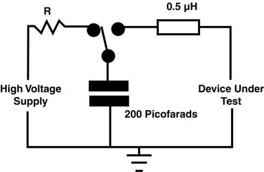
ANSI/ESD STM5.2): Electrostatic Discharge Sensitivity Testing — Machine Model
This Standard establishes a test procedure for evaluating the ESD sensitivity of components to a defined Machine Model (MM). The component damage caused by the Machine Model is often similar to that caused by the Human Body Model, but it occurs at a significantly lower voltage.
ANSI/ESD STM5.3.1: Electrostatic Discharge Sensitivity Testing – Charged Device Model — Non-Socketed Mode
This Standard Test Method establishes a test method for evaluating the ESD sensitivity of active and passive components to a defined Charged Device Model (CDM).
ANSI/ESD SP5.3.2: Electrostatic Discharge Sensitivity Testing. – Socketed Device Method (SDM) – component Level.
This standard practice provides a test method generating a Socketed Device Model (SDM) test on a component integrated circuit (IC) device.
ANSI/ESD SP5.4: Latchup Sensitivity Testing of CMOS/BiCMOS Integrated Circuits. – Transient Latchup Testing – Component Level Suppl Transient simulation.
This standard practice method was developed to instruct the reader on the methods and materials needed to perform Transient latchup testing.
ANSI/ESD STM5.5.1:Electrostatic Discharge Sensitivity Testing – Transmission Line Pulse (TLP) – Component Level.
This document pertains to Transmission Line Pulse (TLP) testing techniques of semiconductor components. The purpose of this document is to establish a methodology for both testing and reporting information associated with TLP testing.
ANSI/ESD SP5.5.2: Electrostatic Discharge Sensitivity Testing – Very Fast Transmission Line Pulse (VF-TLP) – Component Level
This document pertains to Very Fast Transmission Line Pulse (VF-TLP) testing techniques of semiconductor components. It establishes guidelines and standard practices presently used by development, research, and reliability engineers in both universities and industry for VF-TLP testing. This document explains a methodology for both testing and reporting information associated with VF-TLP testing.
ANSI/ESD SP5.6: Electrostatic Discharge Sensitivity Testing – Human Metal Model (HMM) – Component Level
Establishes the procedure for testing, evaluating, and classifying the ESD sensitivity of components to the defined HMM.
ANSI/ESD S6.1: Grounding
This Standard recommends the parameters, procedures, and types of materials needed to establish an ESD grounding system for the protection of electronic hardware from ESD damage. This system is used for personnel grounding devices, worksurfaces, chairs, carts, floors, and other related equipment.
ANSI ESD S7.1: Floor Materials — Resistive Characterization of Materials
Measurement of the electrical resistance of various floor materials such as floor coverings, mats, and floor finishes is covered in this document. It provides test methods for qualifying floor materials before installation or application and for evaluating and monitoring materials after installation or application.
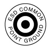
ANSI ESD S8.1: ESD Awareness Symbols
Three types of ESD awareness symbols are established by this document. The first one is to be used on a device or assembly to indicate that it is susceptible to electrostatic charge. The second is to be used on items and materials intended to provide electrostatic protection. The third symbol indicates the common point ground
ANSI/ESD S9.1: Resistive Characterization of Footwear
This Standard defines a test method for measuring the electrical resistance of shoes used for ESD control in the electronics environment.
ANSI/ESD SP10.1: Automated Handling Equipment
This Standard Practice provides procedures for evaluating the electrostatic environment associated with automated handling equipment.
ANSI ESD STM11.11: Surface Resistance Measurement of Static Dissipative Planar Materials
This Standard Test Method defines a direct current test method for measuring electrical resistance. The Standard is designed specifically for static dissipative planar materials used in packaging of ESD sensitive devices and components.
ANSI/ESD STM11.12: Volume Resistance Measurement of Static Dissipative Planar Materials
This Standard Test Method provides test methods for measuring the volume resistance of static dissipative planar materials used in the packaging of ESD sensitive devices and components.
ANSI/ESD STM11.13: Two-Point Resistance Measurement
This Standard Test Method provides a test method to measure the resistance between two points on an items surface.
ANSI ESD STM11.31: Evaluating the Performance of Electrostatic Discharge Shielding Bags
This Standard provides a method for testing and determining the shielding capabilities of electrostatic shielding bags.
ANSI/ESD STM12.1: Seating-Resistive Characterization
This Standard provides test methods for measuring the electrical resistance of seating used to control ESD. The test methods can be used for qualification testing as well as for evaluating and monitoring seating after installation. It covers all types of seating, including chairs and stools.
ANSI/ESD STM13.1: Electrical Soldering/Desoldering Hand Tools
This Standard Test Method provides electric soldering/desoldering hand tool test methods for measuring the electrical leakage and tip to ground reference point resistance and provides parameters for EOS safe soldering operation.
ANSI/ESD SP15.1: Standard Practice for In-Use Testing of Gloves and Finger Cots
This document provides test procedures for measuring the intrinsic electrical resistance of gloves and finger cots as well as their electrical resistance together with personnel as a system.
ANSI ESD S20.20: Standard for the Development of an ESD Control Program
This Standard provides administrative, technical requirements and guidance for establishing, implementing and maintaining an ESD Control Program.
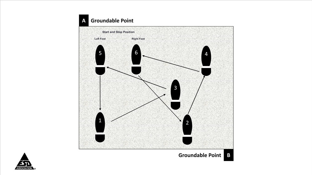
ANSI/ESD STM97.1: Floor Materials and Footwear – Resistance in Combination with a Person.
This Standard Test Method provides for measuring the electrical resistance of floor materials, footwear and personnel together, as a system.
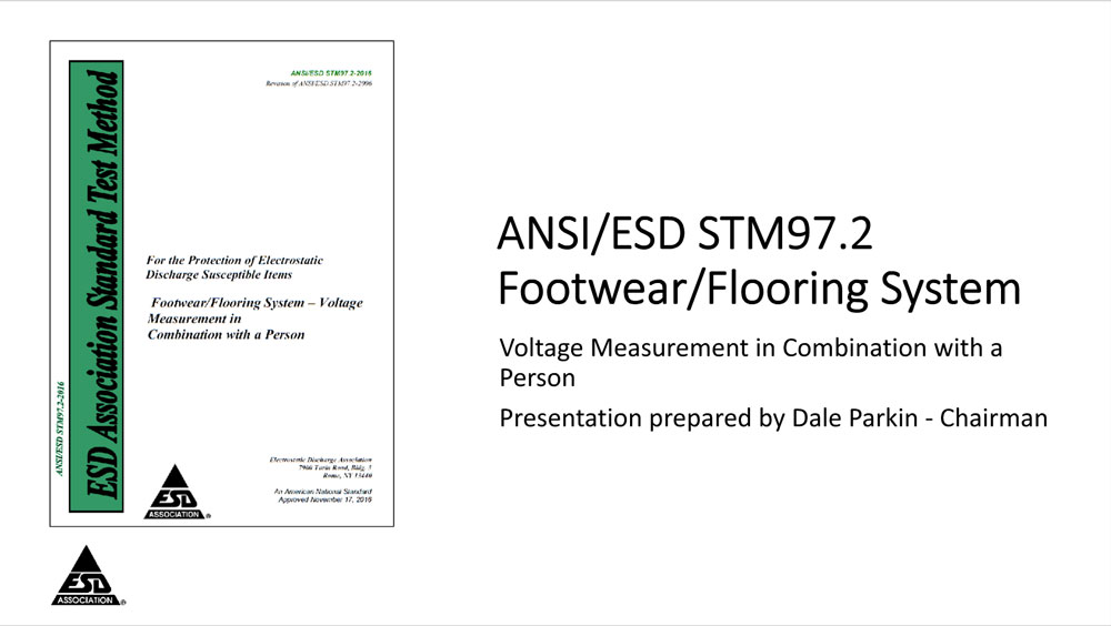
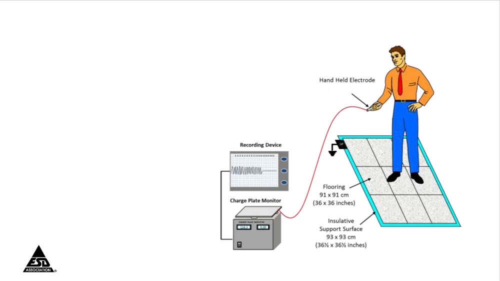
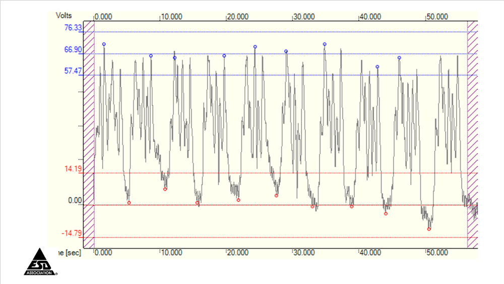
ANSI/ESD STM97.2- Floor Materials and Footwear Voltage Measurement in Combination with a Person
This Standard Test Method provides for measuring the electrostatic voltage on a person in combination with floor materials and footwear, as a system.
Advisory Documents
Advisory Documents and Technical Reports are not Standards, but provide general information for the industry or additional information to aid in better understanding of Association Standards.
- ESD ADV1.0: Glossary of Terms
Definitions and explanations of various terms used in Association Standards and documents are covered in this Advisory. It also includes other terms commonly used in the ESD industry.
- ESD ADV3.2: Selection and Acceptance of Air Ionizers
This Advisory document provides end users with guidelines for creating a performance specification for selecting air ionization systems. It reviews four types of air ionizers and discusses applications, test method references, and general design, performance and safety requirements.
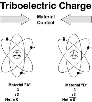
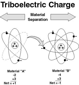
- ESD ADV11.2: Triboelectric Charge Accumulation Testing
The complex phenomenon of triboelectric charging is discussed in this Advisory. It covers the theory and effects of tribocharging. It reviews procedures and problems associated with various test methods that are often used to evaluate triboelectrification characteristics. The test methods reviewed indicate gross levels of charge and polarity, but are not necessarily repeatable in real world situations.
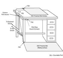
- ESD TR53.1: ESD Protective Workstations
This Advisory document defines the minimum requirements for a basic ESD protective workstation used in ESD sensitive areas. It provides a test method for evaluating and monitoring workstations. It defines workstations as having the following components: support structure, static dissipative worksurface, a means of grounding personnel, and any attached shelving or drawers.
- ESD TR 20.20: ESD Handbook
New handbook provides detailed guidance for implementing an ESD control program in accordance with ANSI/ESD S20.20.